Programmable IO (PIO) for MIDI with the Rasberry Pi Pico
I recently read a few posts on the Simple DIY Electronic Music Project blog about using the Raspberry Pi Pico to interface with synthesizers over MIDI. The Pico is an interesting beast and I was curious how far it can be pushed - how many devices can a Pico control at once? It turns out that it is possible to create a MIDI thru device of up to 25 outputs with PIO doing most of the heavy lifting leaving the main CPUs to handle program logic (and perhaps USB / WiFi / Bluetooth / etc).
People with synths (especially those of us who suffer from GAS1) often need something to copy the output of one device (a keyboard, sequencer, or output from a DAW2) to the input of several other devices (synths, sequencers, drum machines etc.). There are a few niche products on the market that provide this MIDI thru capability, but these are significantly more expensive than the $4 Pico.
The MIDI protocol is transported over a serial communications link. Most microprocessors have one or more UART controllers that handle the transmission of serial data. These UARTs allow the CPU to send a number of bytes in parallel freeing the CPU from having to manage the exact timing of the electrical signals. Most microprocessors have a small number of UART controllers (usually less than 4). Going beyond the limit of the number of UARTs requires the CPU to send tightly timed on/off signals to the GPIOs which wastes a significant portion of the processing time managing input and output tasks.
One barrier to this however is the Pico only has two built in serial (UART) controllers. But it does have a neat feature to avoid having to bitbang a protocol - Programmable IO (PIO).
PIO
The Raspberry Pi Pico provides 8 programmable state machines that run at a fractional multiple of the main clock and allow us to offload input / ouput tasks from the CPU. Each machine is controlled by a very small instruction set with only 32 instruction slots per machine. Programs written for PIO can access and control any of the GPIO pins on the Pico.
Serial MIDI
The hardware MIDI interface operates at 31.25 (+/- 1%) Kbaud, asynchronous, with a start bit, 8 data bits (D0 to D7), and a stop bit. This makes a total of 10 bits for a period of 320 microseconds per serial byte. The start bit is a logical 0 (current on) and the stop bit is a logical 1 (current off). Bytes are sent LSB first.
Raspberry Pi Pico UART
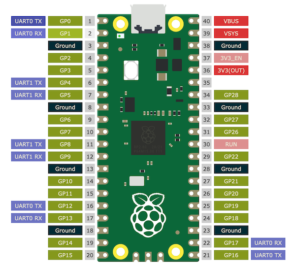
The Raspberry Pi Pico only has two UART transmit/receive (TX/RX) pairs (UART0 and UART1 in the pinout diagram below). PIO allows us to build equivalent functionality on any GPIO pin to extend this limitation. The Raspberry Pi Pico SDK examples contains sample code for a single PIO UART. In this post I'll extend that example so that the PIO code can transmit over any number of pins.
The Existing UART Transmit Example
The example UART TX PIO code handles a single UART transmission, and is configured to 1 start bit (LO), 8 data bits, and then 1 stop bit (HI). We call this 8n1 (the n indicates that there is no parity bit in the protocol).
.program uart_tx
.side_set 1 opt

; An 8n1 UART transmit program.
; OUT pin 0 and side-set pin 0 are both mapped to UART TX pin.

    pull       side 1 [7]  ; Assert stop bit, or stall with line in idle state
    set x, 7   side 0 [7]  ; Preload bit counter, assert start bit for 8 clocks
bitloop:                   ; This loop will run 8 times (8n1 UART)
    out pins, 1            ; Shift 1 bit from OSR to the first OUT pin
    jmp x-- bitloop   [6]  ; Each loop iteration is 8 cycles.
This code configures the programmable io program to be able to set a single pin hi or low while simultaneously running another instruction. It then pulls 32 bits of data from the input buffer into the state machine's output shift register (OSR) and sidesets the Tx pin high to indicate a stop bit. It then sets the x register up as a loop variable to run 8 times while simultaneously setting the start bit. Then we see the meat of the loop, grab a single bit from the output shift and set the Tx pin high or low depending on the that bit. It repeats this 8 times, and then starts again.
An astute reader will notice that there are some extra numbers in square brackets at the end of the line. These add pauses to each instruction of a certain number of instructions. This allows each bit sent on the transmit line to be a standard known length. In this case each bit takes 8 ticks. The first two instructions (pull and setup the loop counter) each take a single tick plus 7 extra ticks. Each time through the loop we see a single clock tick for the output instruction, plus another single conditional jump instruction with 6 extra ticks for a total of 8 ticks. (The pull command is a little different as it may block indefinitely if the output buffer is empty).
The transmit example also sets up the input and output pin parameters, including ensuring that the pin starts out high indicating stop or no data yet. It configures the state machine to run at 8 ticks per cycle (dividing the CPU frequency by 8 times the baudrate to transmit at the required serial frequency). It finally contains some convenience methods to write to the state machine output buffer.
We can take this program, and assemble it to C code using pioasm. This generates a header file which can be included in a standard pico program. An online version of the compiler is at PIOASM.
Modifying the Example to Write Multiple Pins in Parallel
My first attempt at moving from a single pin to 8 pins was to treat the buffer as a transposed
version of what should end up in each pin. E.g. if we want to send abcdefgh to 8 pins (where a-h are
either 0 or 1), then our buffer should contain two 32 bit values: aaaaaaaabbbbbbbbccccccccdddddddd
and eeeeeeeeffffffffgggggggghhhhhhhh. This allows us to send 8 pins of data at once on each output
instruction. We use 2 as the cycles per bit as a simplified unwrapped loop works well enough:
- Pull 32 bits
- Set 8 pins to 0 (start bits)
- Output 8 bits from the output shift register to the 8 pins
- Output 8 bits from the output shift register to the 8 pins
- Output 8 bits from the output shift register to the 8 pins
- Output 8 bits from the output shift register to the 8 pins
- Pull 32 bits
- Output 8 bits from the output shift register to the 8 pins
- Output 8 bits from the output shift register to the 8 pins
- Output 8 bits from the output shift register to the 8 pins
- Output 8 bits from the output shift register to the 8 pins
- Set 8 pins to 1 (stop bits)
// a multi pin uart that send 8 bits at a time by treating the buffer as
// transposed (i.e. byte0 provides LSB0 of all pins, byte1 -> LSB1 etc.)
// buffer is 32 bits, so for 8 x 8-bit pushes, we need two full buffers
// to fill a single UART byte (start-b7-b6-b5-b4-b3-b2-b1-b0-stop)

.program uart_tx
    pull
    mov pins, null [1] ; start bit (0)
    out pins, 8 [1]
    out pins, 8 [1]
    out pins, 8 [1]
    out pins, 8
    pull
    out pins, 8 [1]
    out pins, 8 [1]
    out pins, 8 [1]
    out pins, 8 [1]
    mov pins, !null   ; stop bit (1)
Our configuration is similar to the example code, but removes the sideset code:
static inline void uart_tx_program_init(PIO pio, uint sm, uint offset, uint pin, uint baud) {
    const int PIN_COUNT = 8;
    const int PIN_MASK = 0xFF;
    // the number of PIO cycles that it takes to output a single bit
    const uint cycles_per_bit = 2;
    // the clock divider (number of CPU cycles that each PIO cycle takes)
    float div = (float)clock_get_hz(clk_sys) / (baud * cycles_per_bit);

    // initialize the pins to high indicating the stop bit
    pio_sm_set_set_pins(pio, sm, pin, PIN_COUNT);
    pio_sm_set_pindirs_with_mask(pio, sm, 0xFFFFFFFF, PIN_MASK << pin);
    pio_sm_set_pins_with_mask(pio, sm, 0xFFFFFFFF, PIN_MASK << pin);
    for (int i = 0; i < PIN_COUNT; i++) {
        pio_gpio_init(pio, pin + i);
    }

    pio_sm_config c = uart_tx_program_get_default_config(offset);
    sm_config_set_out_shift(&c, true, false, 32); // shift to right, no autopull
    sm_config_set_out_pins(&c, pin, PIN_COUNT); // Set 8 pins starting at `pin`
    sm_config_set_set_pins(&c, pin, PIN_COUNT); // Set 8 pins starting at `pin`
    sm_config_set_clkdiv(&c, div);
    pio_sm_init(pio, sm, offset, &c); // Load config
    pio_sm_set_enabled(pio, sm, true); // Start state machine
}

static inline void uart_tx_program_putc(PIO pio, uint sm, uint32_t b1, uint32_t b2) {
    pio_sm_put_blocking(pio, sm, b1);
    pio_sm_put_blocking(pio, sm, b2);
}
We compile this using the online pioasm tool which generates a header file (uart_tx.h) to include in our project
The benefit of this approach is that we can send different messages to each transmit line, which allows us to process each output differently before sending. It does however introduce a bit more complexity in the message sending part that runs on the CPU as each set of messages has to be transposed prior to sending or code written to copy each byte to the right bits of the output buffer. E.g.:
// Send the exact same byte to all outputs
void sendByte(uint idx) {
  uint8_t m = messages[idx];
  uint32_t low = (
    ((m >> 0 & 0x01) << 0) +
    ((m >> 1 & 0x01) << 8) +
    ((m >> 2 & 0x01) << 16) +
    ((m >> 3 & 0x01) << 24)
  ) * 0xFF;
  uint32_t high = (
    ((m >> 4 & 0x01) << 0) +
    ((m >> 5 & 0x01) << 8) +
    ((m >> 6 & 0x01) << 16) +
    ((m >> 7 & 0x01) << 24)
  ) * 0xFF;
  uart_tx_program_putc(pio, sm, low, high);
}
The full sketch just writes some test MIDI messages on the output ports starting at PIN2 on the Pico (leaving UART0 to handle PIN0 and PIN1):
// A test harness for 8 pin UART TX on a single PIO State Machine
// Test project https://wokwi.com/projects/344410676217774675
// uart_tx.h source
#include "pico/stdlib.h"
#include "hardware/pio.h"
#include "uart_tx.h"

// start at pin 2, so if we want we have UART0 on GP0 and GP1
const uint pin = 2;

// NOTE the simulator doesn't seem to hit this exactly (on my 2015 macbook)
// It ends up being slow by about 6% YMMV
const uint baud = 31250;
const PIO pio = pio0;

uint sm;

void setup() {
  uint offset = pio_add_program(pio, &uart_tx_program);
  sm = pio_claim_unused_sm(pio, true);
  uart_tx_program_init(pio, sm, offset, pin, baud);
}

// Some test messages
uint8_t messages[12] = {
  0x80, 0x3C, 0x00, // Note Off Channel 1, Middle C, Velocity 0
  0x90, 0x3C, 0x7F, // Note On Channel 1, Middle C, Velocity 127
  0x80, 0x3D, 0x00, // Note Off Channel 1, Middle C, Velocity 0
  0x90, 0x3D, 0x7F  // Note On Channel 1, Middle C, Velocity 127
};
uint counter = 0;

void loop() {
  // pull 3 message bytes off
  sendByte(counter++);
  sendByte(counter++);
  sendByte(counter++);
  counter %= 12;
  // delay(1);
  // delayMicroseconds(100);
}
There's not much to this. Copy the pio program into the first PIO (the Pico has 2 PIOs each with 4 state machines), and start it running at 31.25kHz sending some note on/off messages.
Simulating the output
We load this into the simulator and run it capturing the outputs on a simulated logic analyzer. The following configures a simulated pi pico, with a logic analyzer hooked up to monitor the pins.

{
  "version": 1,
  "author": "Joshka",
  "editor": "wokwi",
  "parts": [
    {
      "type": "wokwi-pi-pico",
      "id": "pico",
      "top": 6.35,
      "left": 153.6,
      "rotate": 1800,
      "attrs": { "env": "arduino-community" }
    },
    {
      "type": "wokwi-logic-analyzer",
      "id": "logic1",
      "top": 165.4,
      "left": 9.05,
      "rotate": 90,
      "attrs": { "bufferSize": "3000" }
    }
  ],
  "connections": [
    [ "pico:GP0", "$serialMonitor:RX", "", [] ],
    [ "pico:GP1", "$serialMonitor:TX", "", [] ],
    [ "pico:GND.1", "logic1:GND", "black", [ "h0" ] ],
    [ "pico:GP2", "logic1:D0", "green", [ "h0" ] ],
    [ "pico:GP3", "logic1:D1", "green", [ "h0" ] ],
    [ "pico:GP4", "logic1:D2", "green", [ "h0" ] ],
    [ "pico:GP5", "logic1:D3", "green", [ "h0" ] ],
    [ "pico:GP6", "logic1:D4", "green", [ "h0" ] ],
    [ "pico:GP7", "logic1:D5", "green", [ "h0" ] ],
    [ "pico:GP8", "logic1:D6", "green", [ "h0" ] ],
    [ "pico:GP9", "logic1:D7", "green", [ "h0" ] ]
  ],
  "serialMonitor": { "display": "auto", "newline": "lf" }
}
Once we finish running this for a bit, we grab the output and load it into Pulseview to see how we went. You may need to configure the analysis to be slightly lower baud rate than we're actually anticipating. I'm unsure if this is a simulator bug or just a performance issue. To work out the exact frequency to use, measure the time between the start bit and the first bit and find the inverse. On my machine, this was about 6% slower than real time - YMMV.

Extending this to any number of bits
The first attempt works, but if all we want is to send the same data to every port we can simplify and ditch the buffer transposition code that runs on the CPU. This also avoids the difficulty of what to do with odd pin counts that won't neatly fit in 32 bits.
In this approach, we use the y register to count down the bits like the original example uart tx code. We load each bit of the output buffer bit by bit into the x register, and either write all zeroes or all ones to every pin. We use 4 cycles per bit as this is necessary to allow the right number of jump instructions etc. The logic for this is:
- Pull
- Output 0 to all pins (start bit)
- Loop 8 times:
- If the next bit is 0, putput all zeros otherwise output all 1s
- Output 1 to all pins (stop bit)
// a multi pin uart that send 16 bits at a time by copying each bit LSB to the output
// different from the previous version in that this just plain copies a normal byte,
// rather than having a larger buffer that can set every pin differently.
// so the input is a single byte in the buffer, rather than one byte per bit
// 16 isn't at all special in this, it should work from 1 to whatever number of
// consecutive pins you have available (pico has 0-22)

// only tested at https://wokwi.com/tools/pioasm so far, not on a real
// device see also https://wokwi.com/projects/344410676217774675
// This version https://wokwi.com/projects/344453034004185682

.program uart_tx

    pull [2]
    mov pins, null  ; output start bit to all pins
    set y, 7        ; y is bit counter 7 to 0
loopbits:
    out x, 1        ; get LSB from OSR
    jmp !x, zerobit
onebit:
    mov pins, !null ; output one to all pins
    jmp y--, loopbits
    jmp end
zerobit:
    mov pins, null  ; output zero to all pins
    jmp y--, loopbits
    nop
end:
    nop
    mov pins, !null ; output stop bit to all pins

% c-sdk {
static inline void uart_tx_program_init(PIO pio, uint sm, uint offset, uint pin, uint baud) {
    const int PIN_COUNT = 16;
    const uint32_t PIN_MASK = 0xFFFF;
    // the number of PIO cycles that it takes to output a single bit
    const uint cycles_per_bit = 4;
    // the clock divider (number of CPU cycles that each PIO cycle takes)
    float div = (float)clock_get_hz(clk_sys) / (baud * cycles_per_bit);

    // initialize the pins to high indicating the stop bit
    pio_sm_set_set_pins(pio, sm, pin, PIN_COUNT);
    pio_sm_set_pindirs_with_mask(pio, sm, 0xFFFFFFFF, PIN_MASK << pin);
    pio_sm_set_pins_with_mask(pio, sm, 0xFFFFFFFF, PIN_MASK << pin);
    for (int i = 0; i < PIN_COUNT; i++) {
        pio_gpio_init(pio, pin + i);
    }

    pio_sm_config c = uart_tx_program_get_default_config(offset);
    sm_config_set_out_shift(&c, true, false, 32); // shift to right, no autopull
    sm_config_set_out_pins(&c, pin, PIN_COUNT); // Set 8 pins starting at `pin`
    sm_config_set_set_pins(&c, pin, PIN_COUNT); // Set 8 pins starting at `pin`
    sm_config_set_clkdiv(&c, div);
    pio_sm_init(pio, sm, offset, &c); // Load config
    pio_sm_set_enabled(pio, sm, true); // Start state machine
}

static inline void uart_tx_program_putc(PIO pio, uint sm, uint32_t b1) {
    pio_sm_put_blocking(pio, sm, b1);
}
%}
The test harness, sketch etc. is equivalent and a simulated version can be seen at: https://wokwi.com/projects/344345628967436882
void loop() {
  // pull 3 message bytes off
  sendByte(counter++);
  sendByte(counter++);
  sendByte(counter++);
  counter %= 12;
  // delay(1);
  // delayMicroseconds(100);
}

void sendByte(uint idx) {
  uint8_t m = messages[idx];
  uart_tx_program_putc(pio, sm, (uint32_t)m);
}
Wrapping up
While this exists only in simulated form right now, we can see that the Pico could indeed run a copy based UART to implement MIDI thru on every pin from PIN0 to PIN22 (PIN23-25 are used internally). A DIY version of Kenton's 25 port version might set you back $4 for the pico, and $1.50 per port (plus incidental wires breadboard etc.), about $41 total. The cool part about this is that it would be possible to sync two of these with a higher bandwitch protocol than midi for easy latency free expandability (whereas daisy chaining today introduces ~1ms lag for an average 3 byte message at 31.25kHz). We can also extend this to USB, Wifi (using the Pico-W), and potentially event bluetooth MIDI (once this is enabled on the Pico-W).
Gear Acquisition Syndrome.
Digital Audio Workstation. E.g. Ableton Live, Bitwig, etc.